-
What a Badly Set Seat and Tiller Actually Feels Like
-
Set Seat Travel on the Track First
-
Why the Far-Pedal Knee Check Sets Seat Reach
-
Raising the Tiller Without Passing the Insertion Line
-
Four Stem Bolts and the Downward Push Test
-
Squaring the Handlebar to the Front Wheel
-
Why a Small Bar-to-Wheel Offset Changes Tracking
-
What These Pages Do Not Answer for Fleet Use
-
Do You Need a Dealer for This Adjustment?
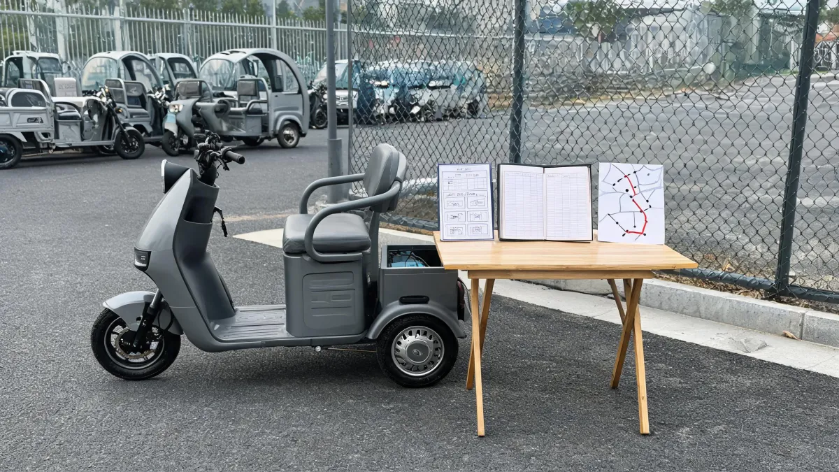
Two SBST-0921 trikes can leave the same crate and feel like different machines. On the first, the seat sits wherever the last person in the shop left it and the tiller rides at shipping height, so a taller rider pedals with a locked knee and the bar sits slightly off the front wheel, and the trike wanders down the driveway while the rider blames the steering. On the second, someone worked through a fixed order: seat first, tiller height second, bar-to-wheel plane last, with a check after each step. Only the setup differs.
The claim worth making up front is that seat and steering here are one setup rather than two preferences, and the setup runs seat first, because tiller height and bar-to-wheel alignment only mean something once hip position has fixed where the hands and eyes land. Everything below is scoped to the Worksman Side by Side Team Dual SBST-0921 and the instructions printed for that model; other trikes use different stems and seats and should be set from their own manuals. What follows is the order, the reason behind each step, and the observable check that tells you a step is done.
What a Badly Set Seat and Tiller Actually Feels Like
The delivered state of this trike is not a fit. On the SBST-0921 the stem is not tightened at the factory for height or alignment, which makes whatever bar position you see in the crate a shipping state rather than a decision made for a rider. Two consequences follow. The seat can be anywhere along its track, so a rider with a longer inseam reaches for the pedal with a straight leg and rocks the pelvis to get around the top of the stroke. And the bar can sit slightly off the front wheel, so the hands hold a correction the whole time the trike is rolling. Neither fault announces itself as a setup problem. The rider feels a long reach and a trike that will not track, and starts suspecting tires and frame alignment.
Set Seat Travel on the Track First
The seat comes first, and the manual's order for it is short. Thread the T bolt, still upside down, into the bottom of the seat; that bolt is what clamps the seat assembly to the track underneath. Slide the seat along the track to the position where the leg is slightly bent at the knee with the pedal at its furthest point away from the rider. Then tighten the bolt so the seat is secure and no longer slides across the track.
That last clause is the pass check, and it should be treated as one. A seat that still creeps along the track under pedaling load will not hold the position you just chose, and the reach you set is gone by the end of the first block. Do the bar first and you fit it to a hip position that is about to move.
Why the Far-Pedal Knee Check Sets Seat Reach
Here is where we would take a position: set seat reach from the far-pedal knee check, not from how the trike feels on a flat driveway. The reason is mechanical. The furthest pedal point is the longest the leg has to reach during the stroke, so a locked-straight knee there leaves the pelvis no margin and it rocks toward the pedal to complete the circle. The slight bend the manual asks for is exactly that margin, which means the variable being measured is the seat's position on the track rather than the rider's pedaling style.
The manual states a qualitative standard, not a measurement, so a boundary belongs here. Two riders with different leg lengths will legitimately stop at different points on the same track, and handing the trike to a different rider means redoing the slide rather than sharing one setting. A crew that writes a track position on the seat rail for the next shift is writing down one person's fit, not the trike's.
Raising the Tiller Without Passing the Insertion Line
Tiller height is limited from below, not from above. Lift the tiller to a comfortable position and tighten the four stem bolts with a 5mm hex key; the factory leaves that stem loose for height and alignment precisely so this adjustment is possible on delivery. The constraint is the minimum insertion line marked on the stem, and the stem must be inserted to that line.
The mark matters because the stem carries steering load only over the length actually seated inside the steerer tube; above the line less material is engaged while the lever arm from the grips gets longer. Which means the line caps how far the stem can be pulled up, and arm comfort alone is the wrong criterion for setting height. The pages name no alternative stem for a taller rider, so that stays a supplier question rather than something to improvise with spacers.
Four Stem Bolts and the Downward Push Test
Bolt feel on the key is a poor test, so the manual supplies a load test instead. With the four stem bolts tightened, make certain the stem is tight and the tiller remains up even while exerting downward pressure. Downward pressure loads the clamp in the same direction a rider's weight pushes when braking or pulling on the bar, so the check observes the joint under the load it will actually see in service.
A clamp that feels snug on the key can still rotate under that push, which is why the pass condition is written as an outcome rather than a torque value. The manual gives no torque figure for these bolts, so the push test is the acceptance criterion, and guessing at a number adds nothing you can check.
Squaring the Handlebar to the Front Wheel
Alignment is the last step because it can only be done while the clamp is still free to move. Sight the handlebar against the plane of the front wheel; once it is straight, tighten the central alignment bolt on the stem with a 6mm hex or an adjustable wrench depending on the style of stem, so that the handlebar and front wheel are aligned. Confirm the tool size on your own stem before turning anything, because that same passage notes stem specifications can change without written notice and a build can differ from the drawing in your hand.
Tighten the alignment bolt first and you simply freeze whatever error is present. Re-sight the bar against the wheel after the final turn instead of assuming the act of tightening preserved the relationship you set.
Why a Small Bar-to-Wheel Offset Changes Tracking
A small offset does not read as a fault, which is what makes it expensive. Steering rotates the wheel plane about the stem axis, so a bar mounted off-square leaves the rider's straight-ahead hand position pointing somewhere other than the wheel's straight-ahead. It comes down to a correction held continuously at the grips: the hands steer slightly left or right to make the trike run straight. Because the error is small, nothing snaps or grinds; it surfaces as wandering on a straight stretch and forearm fatigue late in a shift. A rider who notices that tends to suspect tires, frame alignment or seat position, which is how the seat gets adjusted twice while the bar is never checked at all.
What These Pages Do Not Answer for Fleet Use
The instructions covering this model give tools and observable pass conditions, and they stop there. There is no torque figure for the four stem bolts or the central alignment bolt, no per-rider weight guidance, and no re-check interval for a trike in daily service. That note about stem specifications changing without written notice is the reason tool sizes and part numbers are per-build confirmation items rather than constants a fleet writes down once.
For a fleet operator the practical reading is that the procedure is reproducible while the hardware record is not. Keep the seat-then-tiller-then-alignment order, note which rider each unit was set for, and get the torque figure and the current stem specification from the supplier in writing before the units go into service. Those are procurement questions, not service steps to invent in the bay.
Do You Need a Dealer for This Adjustment?
Nothing in the printed instructions requires a dealer. The named tools are a 5mm hex key for the four stem bolts and, depending on stem style, a 6mm hex or an adjustable wrench for the central alignment bolt, and each step ends in something you can watch rather than a torque number: a seat that stays put on its track, a tiller that holds under downward pressure, and a bar square to the front wheel. Fail any one of the three and the setting is not finished. That is the whole acceptance test, and it runs in a driveway.
Suppose a fleet takes delivery of six units and one technician sets them all in the same order against the far-pedal check. The settings stay comparable from unit to unit, and a rider complaint can be traced to a rider rather than to a machine. We would still take the far-pedal check over a driveway impression on the sixth trike as readily as on the first. What none of these pages settles goes to the supplier as a question rather than into the bay as a guess.